 the
Red Fox says : "I recommend that you listen to your engine
in this way and get used to what it should sound like. In fact
listen to it all over the engine casings."
the
Red Fox says : "I recommend that you listen to your engine
in this way and get used to what it should sound like. In fact
listen to it all over the engine casings."Honda NT650 "Deauville" - Tappets check / adjust
(includes changing the Sparking Plugs)
This page shows you how to check and adjust the cylinder head tappets of your Deauville motorcycle.
Skill : 3. Tools : 1. Personally dirty : 2. Work mess : 2. Space : 2. Time : a day, because whilst actually doing the tappets is simple enough, there is a great deal of work involved in removing enough other components to give the necessary access. For a "first timer" I'd say the time involved would be an easy weekend's work. Don't let the "3" rating put you off - this reflects far more on the amount of work rather than the technical difficulty.
Skill levels explained. Return to the Deauville Web Resource
This page refers to a UK specification NT650V4 Deauville and I can't speak for what differences there might be on other variants. I welcome amplification of any points from other owners - by all means contact me with a view to providing comparable photos, which I'll credit accordingly.
All the tools, hands, and bike in the pictures are the author's. I am very receptive to comments and suggestions, but you use these pages entirely at your own risk. I recommend wearing surgical gloves when working with oils and other fluids, or just to help keep your hands clean.
All nut and bolt sizes are given for the spanner size required to fit them.
Tools : 10mm and 17mm sockets, extension bar and ratchet handle; Allen key set including a 10mm; feeler gauges; pliers; spark plug wrench; torque wrench.
Remove the side fairings, petrol tank, air filter with its housing, and radiator.
Yes, there is a lot to do - but since a Honda dealer will charge you between £250 and £300 for this work, you can save yourself a lot of money. Probably enough to cover the road tax and insurance for a year - isn't that worth a weekend of your time?
Why is this job necessary anyway?
The inlet and exhaust valves are opened by a camshaft which is chain driven from the crankshaft to ensure accuracy. As the crankshaft is driven round by the pistons, the cam chain is pulled round and this motion is then transmitted to the camshafts (one for each cylinder in a V-twin engine). As the cams rotate, shaped lobes push up rocker arms which pivot about their centre, pushing down their other ends which in turn push down on the valve heads, opening them against powerful spring pressure and thus allowing either fuel/air mixture in, or exhaust gas out. As the cam rotates a little further, the height of the lobes decreases and the powerful valve springs close the valves, sealing the inlet or exhaust gaps.
You can't have the rocker arms directly fixed to the valve tops, or resting immediately on them, due to metal expansion as the engine heats up - this part of the engine gets extremely hot. If the rocker arms didn't have a clearance between them and the valve tops, expanding metal would make the valves be always fractionally open, and the seal would be compromised. So a very small clearance for heat expansion is necessary, which can be adjusted by means of a screw and locking nut.
This valve or tappet clearance is 5/1000ths of an inch ("five thou") for each cylinder's two inlet valves and 7/1000ths of an inch ("seven thou") for each cylinder's single exhaust valve. In those funny foreign measurements, that would be 0.14mm and 0.20mm respectively. The clearances are different because the inlet valves, constantly bathed in a rush of cool fuel and air, don't get as hot as the exhaust valve, which is constantly bombarded with hot, burnt fuel mixture. Logical if you think about it.
As the engine clocks up the 1000s of miles, there is a tiny but progressive amount of wear in the valve and actuating mechanism which causes the valve clearances to increase - it is rare for them to decrease. This results in what is called "tappet rattle" which is when you can hear the rocker arms striking the valve tops, as a distinct clattering noise. There is also a degradation in performance and economy, and can cause serious engine damage if the clearances get badly out of specification.
The classic way to detect tappet rattle is to use a play stethoscope, or a long metal bar. Place one end against the cylinder heads (don't get near the spark plug leads or you might get a nasy shock) and the other end in your ear. Idle the engine and listen. Regular whirrings are fine but a machine-gun or marked clattering sound needs investigation.
 the
Red Fox says : "I recommend that you listen to your engine
in this way and get used to what it should sound like. In fact
listen to it all over the engine casings."
Fortunately the Deauville's service interval of 8,000 miles for tappet checks means that this job is only likely to crop up about once a year, obviously depending on what mileages you are covering. That's just as well because although adjusting the tappets is easy enough once you get to them, it's a case of removing parts A, B, C, D and E to let you get to part F- the part you want to actually work on.
I hope I haven't put you off. The work is technically quite easy.
|
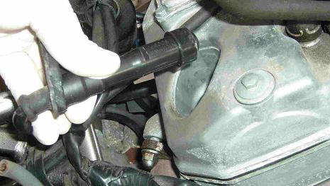
Pull off all four spark plug leads. The one shown here is the deeply recessed one to rear cylinder's right hand lead. |
 |
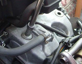 |
Use pliers to release the spring clip securing the fat rubber engine breather hose and pull the hose away from the cover. Use your 10mm socket to undo the two bolts securing the rear cylinder's rocker box cover and remove the cover. In the photo the right hand bolt has already been removed. You can get the rear rocker box cover off without removing the air filter box, but not the front cover. |
|
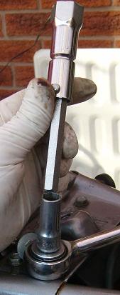
Two of the Deauville's sparking plugs are deeply recessed and you'll need the spark plug spanner from the bike's tool kit to be able to reach them. A socket on the end of the tool will make life easier for you. Here is where you can buy the special plug spanner if you can't find yours. |
 |
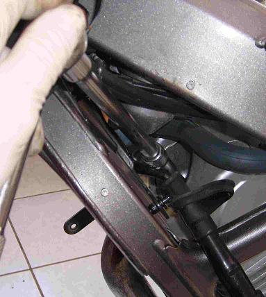 |
Remove
all four of the spark plugs -as you see from the photo, the front cylinder
left hand plug is at a steep angle in towards the centre of the bike,
be patient as the angle can be awkward to get right until you get the
hang of it.
|
|
The front right hand plug is much easier to deal with. |
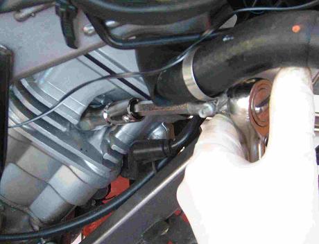 |
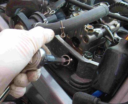 |
As is the rear cylinder left hand spark plug. |
|
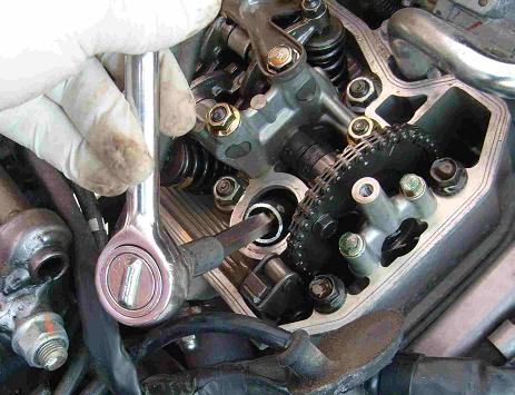
But the rear cylinder's right hand plug is another of the awkward angle ones. After removing the spark plugs, stuff a rag or a ball of kitchen roll into the plug holes, to stop anything falling in. |
 |
 |
|
|
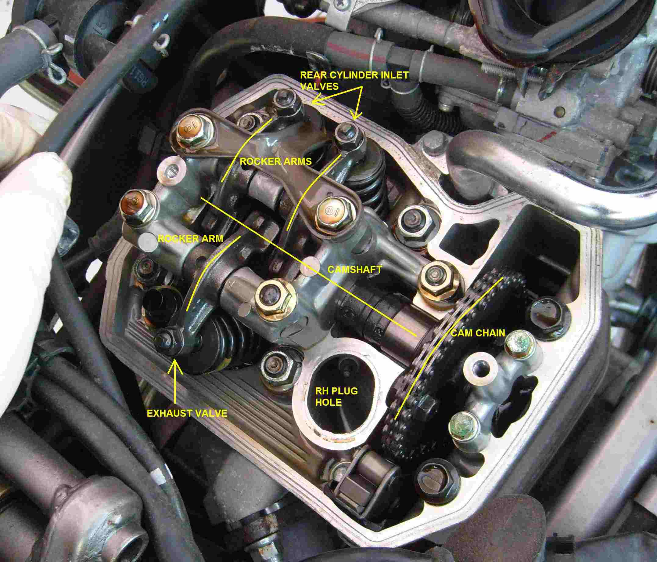
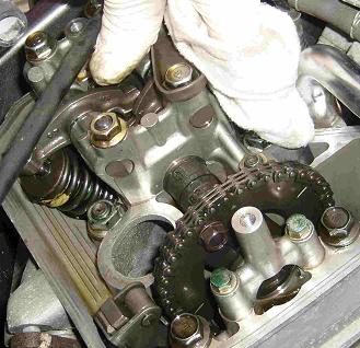
General view inside the rear cylinder head after removing the rocker box cover. The valve stems and rockers upper centre are the two inlet valves which draw their fuel/air mixture from the right-hand carburettor, the intake of which is just visible at the top right of the picture. The single exhaust valve and its rocker arm at at the bottom left of the head, and the curvy chrome pipe carries coolant. |
|
 |
Colin Miller comments - with regard to accessing the front cylinder head - "When I did the tappets, to access the front cylinder cover I removed the thermostat housing as I simply couldn't get access with my hands; but now that I have done it once I probably could work around that." Use your pliers to unclip the front cylinder's engine breather pipe, and pull the pipe away from the rocker box cover. |
|
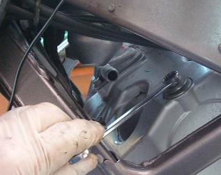
Remove the front cylinder's two rocker box bolts. These are harder to get at and I found that a 10mm ring spanner was the only way to reach and loosen the left hand front bolt.
|
 |
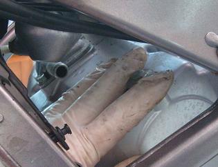 |
Once it's loose, reach in with your fingertips and unscrew it all the way out. |
|
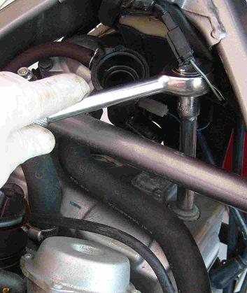
The
front cylinder's right hand rocker box bolt is easier to get off, but
you might find that a short extension bar, or none at all, is easier to
use than the longer one I used earlier.
|
 |
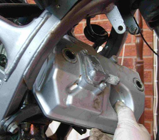 |
With both the rocker box cover bolts removed, wriggle off the front cover, forwards and to the right hand side. It's quite an art to get this cover right off, but be patient and ease it away. If the thick rubber gasket should be dislodged from the bottom edge of either of the covers, take care not to tear it, and then replace it once the cover is right off. With both covers removed you can get at the valve gear for clearance checking and making any necessary adjustments. The procedure is very similar for both cylinders. The front cylinder's two inlet valves face backwards, towards the rear cylinder's two inlet valves which face forwards. The single valve for each cylinder is that for the exhaust. |
|
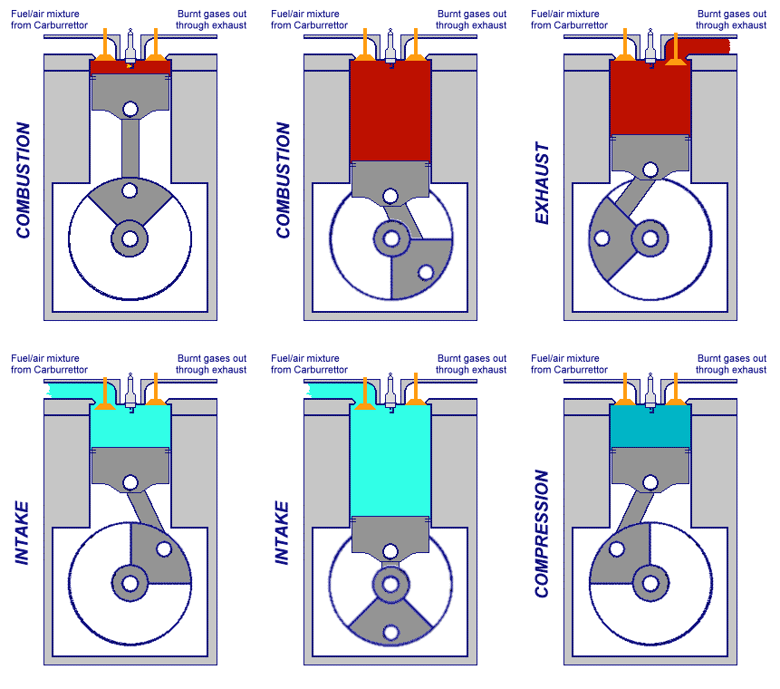
The graphic here demonstrates the 4 stroke cycle; intake, compression, combustion, exhaust (popularly called suck, squeeze, bang, blow). At the start of the induction stroke, the inlet valve(s) open to allow fuel/air mixture to be drawn into into the combustion chamber as the descending piston creates a vacuum above it. At the bottom of the induction stroke the chamber is full of fuel/air and the inlet valve(s) close. The rising piston compresses the fuel mixture as a compressed gas will explode with greater power than uncompressed. At the top of the compression stroke, the sparking plug ignites the mixture and the piston is driven back down its bore, rotating the crankshaft and providing power to the engine. At the bottom of the ignition stroke, the exhaust valve opens and the rising piston pushes out the burned mixture. Then it all happens again. If you are doing 80 mph on your Deau this cycle is happening 1,500 times a minute per cylinder. Scary isn't it. We will work on one cylinder at a time, first the front one, To check the clearances it is first necessary to ensure that the valves are completely closed. This can't be done by a simple visual inspection, so Honda have made it easy for us to tell by casting a special mark on the camshaft to show when the piston inside the cylinder is at Top Dead Centre, popularly called TDC. But there is a snag. Only when the piston is as TDC on the compression stroke are the valves all shut - at TDC on the exhaust stroke, the exhaust valve is not yet closed and the inlet valves are just thinking about opening. |
 |
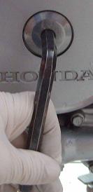 |
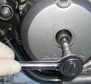
How do we tell the correct stroke? Go round to the left hand side of the Deau and locate the big circular port shown in this photo. Use your 10mm Allen key to unscrew and remove the inspection port. This exposes the left hand end of the engine crankshaft, which has a handy 17mm nut on the end. This large port cover is quite soft metal and may become stuck, or even damaged, especially around the hex hole where the Allen key fits in. If you need to replace it, the part number is "90087KT7000, Cap 30mm". If you can't remove it because it's stuck or the hole is chewed up, first soak it in ACF50 overnight. Then you'll need a large screwdriver and a rubber hammer. Place the tip of the blade on the perimeter of the cap with the blade facing towards the centre, and tap in a small chink so that the screwdriver's edge can get a good grip on the soft alloy of the cap. Now give the screwdriver's handle some smart blows with the rubber hammer and try to knock the soft cover around in the anticlockwise (unscrew) direction. As soon as the cap starts to move and unscrew, you should be able to get it out with more conventional methods! Ensure that the gearbox is in neutral, and the ignition is off. |
|
Use your 17mm socket and ratchet handle to locate on the crankshaft end and get ready to wind the crankshaft slowly round anticlockwise. As you tickle the crankshaft round anticlockwise, look closely at the exposed cam chain and valve gear, you'll see them start to move. If this is your first excursion into engine spannering, it's a profound step forward for you as you can now see how things happen as the engine is running. What you are looking for is a tiny arrow or chevron cast into the steel sprocket which carries the cam chain. When this is at the vertical in relation to the line of the cylinder - remembering that the engine cylinder is angled forward - the piston is at TDC. |
 |
 |
|
|
This photo shows you the chevron just past the vertical - I've done this so you can see what you are looking for. The aluminium pillar is where the rocker box bolt screws in and is the reference point for the vertical line. Remember that THIS photo just shows you what you are looking for, not where to correctly place it. Turn the engine using your ratchet handle until the arrow timing mark on the cam sprocket is at the maximum upper part of its travel. It should then be concealed behind the aluminium pillar, when viewed square on from alongside. To further help you, there are two scribe lines on the sprocket, which lie parallel to the cylinder head's lip once the piston is at TDC. You can see these scribe lines on the above photo. |
|
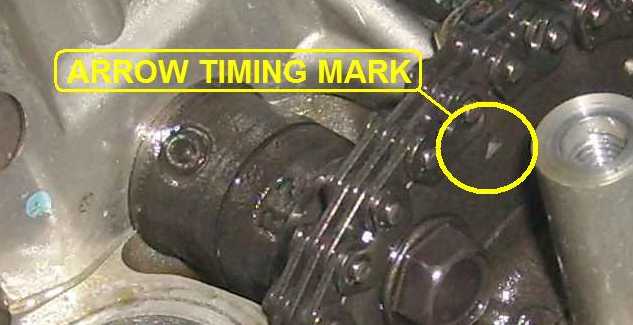 |
This photo makes it look as if the timing mark is past the vertical, but it's an optical illusion due to the camera angle being from the front. In fact the mark is immediately behind the pillar. One quite good way to find out if a cylinder's piston is at top dead centre is to slide a wooden or metal rod through the spark plug hole and rest it on top of the piston. Holding the rod in one hand as the engine is gently rotated, you will be able to feel the rod move with the piston. When the rod has reached its highest point, that is top dead centre, although you won't know whether it's the compression (correct) or exhaust (wrong) stroke. Just be careful not to trap the rod anywhere as the engine turns, and if you use a wooden one, not to break off the end inside the engine! So now you have the front cylinder at TDC - but which stroke - compression (correct) or exhaust - (wrong). How do you tell? This is easy and is called a clack test. |
|
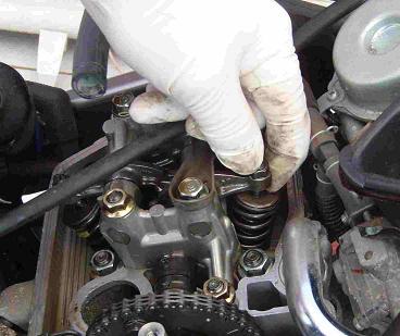
For each valve in turn on the cylinder you are working on, grip the end of the valve rocker in your fingers, directly above the valve, as you see in the photo. Now give each one a good rattle up and down. If all three valves clack, they are not under tension, and the valves are closed at TDC on the compression stroke. This is correct. If they don't clack - and you should be able to feel this movement as well as hear it - the valves are under compression at TDC on the exhaust stroke. This is incorrect, so use your ratchet handle to rotate the crankshaft a full circle, and check the timing mark - or rod, if you used that method - is again at the top. Repeat the clack test.
|
 |
 |
If your feeler gauge set doesn't have a single blade of the required 5/000ths thickess, it's fine to slide a 2/000 and a 3/000 together to make up the required 5/000. Just add up the numbers carefully, and ensure that no unwanted feeler blades are stuck between the ones you actually want. Once all the valves are clackificatious, take the 5/000ths of an inch feeler gauge (aka five thou or 0.005") - or 0.15mm in funny foreign thingies - and choosing one of the two inlet valves, slide the feeler gauge between the top of the valve stem and the underside of the rocker arm. The gauge should be a close sliding fit, not quite bending up as you slide it into the gap. If it won't go in at all, the gap is too narrow. If it goes in and slides about very freely, the gap is too wide. |
|
To adjust the valve clearance, leave the feeler gauge in place and use a 10mm ring spanner to loosen the locknut and your pliers to very gently turn in or out, as necessary, the square-headed adjusting screw. It's important not to push down on the mechanism as you do this. As you adjust the clearance, slide the feeler gauges in and out until they are trapped and won't move. Then unscrew the adjuster just a tiny amount until the feeler gauge can just be withdrawn. Whilst holding the adjuster screw firmly in position with the pliers, tighten the locknut to a good firm finger tight and then use your torque wrench - and if you don't have one, or don't use it, you must be completely mad - to tighten the locknut to 16 ft/lbs. Repeat the feeler gauge test again and re-adjust if necessary, as fully tightening the locknut can slightly reduce the valve clearance. Repeat the procedure for the other intake valve, using the same feeler gauge. |
|
|
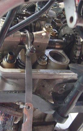
Choose the 7/000ths of an inch feeler (aka seven thou or 0.007") - or 0.2mm - and check/adjust the exhaust valve clearance. Here, the single front exhaust valve clearance is being checked. Notice the 0.2mm feeler gauge. For the rear cylinder, rotate the crankshaft again to get the cylinder to TDC, this time watching for the arrow timing mark or horizontal scribe lines on the rear cam sprocket. These marks are on the left hand side of the cam so you will be able to see them as you nudge the crankshaft round. The technique is the same as for the front cylinder. Don't forget the clack test. |
 |
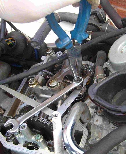 |
Here, the inlet valve clearances are being adjusted on the rear cylinder. FIRST TIMERS - go slow and easy, don't rush!" |
 |
 |
|
After
setting the valves, it's worth cleaning the rocker box heads. I use Mother's
Mag and lots of elbow grease. The rear cover collects most of the road
dirt, whereas the front cover, shielded by the radiator, generally stays
reasonably stain free. Above left - before cleaning : above right - afterwards.
|
|
|
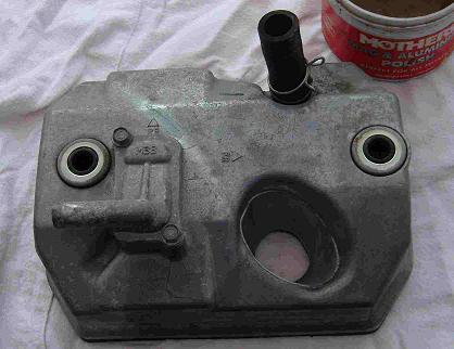
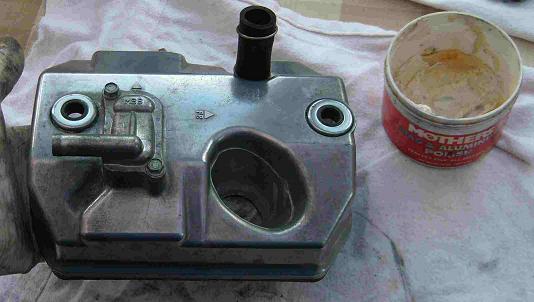
If you forget which rocker box cover goes on which cylinder head, this is the correct orientation. The rear cover is the one with the thick breather pipe connection to the air cleaner box.
In fact the covers are cast identically - but the front one has the breather pipe junction blanked off! |
|
|
Before replacing the covers, clean the mating surfaces to ensure no small debris particles can cause an oil weep. It helps to seat and seal the rubber gaskets if you smear a little oil around them before refitting. Check that the covers have their thick rubber gaskets in place and slide the covers back in place and tighten the holding bolts. |
 |
|
Honda claim that the bolts should be torqued to 7 ft/lbs. I disagree and recommend 6 ft/lbs, for the simple reason that years of working on CX500 engines taught me that the bolts are undone frequently enough to warrant caution regarding wear on the threads into which they engage. These are soft aluminium alloy and whilst a Helicoil repair is easy enough, it's a right pain if you strip out a thread because of over-tightening. In fact there is no oil pressure inside the rocker box covers and no reason for the two bolts to be much more than a really good finger-tight. If you are paranoid about tired and worn threads, set the bolts to 5 ft/lbs torque. If there should be an oil weep, the bolts can be easily reached and tightened a little more. Don't forget to re-attach the breather pipes on the covers, and secure then with their spring clips. Replace the spark plugs with either NGK DPR8EA-9 or their expensive but longer-lasting NGK Iridium equivalents, DPR8EIX-9.
|
|
|
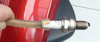
When reinserting the spark plugs, take great care to engage the threads correctly, as two of the plugs as you have seen are at rather awkward angles. One excellent tip is not to use the spark plug spanner to engage the threads. Push a length of plastic aquarium pipe over the spark plug top and use that to tickle the plug into the correct position. If by mischance you have not correctly lined up the plug with its socket in the cylinder head, the pipe will slip off the plug before exerting enough "twist" to cross-thread or damage the engine. Only when the plug is being screwed in quite cleanly and easily should you swap the plastic pipe for the proper spanner. |
 |
|
|
Wire
brush clean the old plugs and stash them in your tail cone as spares.
You might not need them - but another rider might do!
|
Replace the radiator, air filter and its box, fuel tank and side fairings, and you're done.
You are welcome to comment on these pages but you must manually remove the extra 'z' from the email address.