Honda
NT650 "Deauville" - fit the lower foot guards
This page
shows you how to fit the lower foot guards (Honda call these the "Wind
Lower Shield") to your Deauville motorcycle. These extend the bottom
edge of the fairing to give better weather protection to the shins and feet.
Skill
: 2. Tools : 1. Personally dirty : 1. Work
mess : 1. Space : 1. Time : expert 45 minutes,
average 60 minutes, "first-time" 90 minutes.
Skill
levels explained. Return to the Deauville
Web Resource
All
nut and bolt sizes are given for the spanner size required to fit them.
Tools : 8mm,
10mm, 12mm sockets; 12mm ring spanner; ratchet handle and extension bar; Allen
key set; hand or electric drill; 4mm and 10mm drill pieces; sharp knife.
The lower
foot guards and their mountings come as a complete kit from your Honda dealer
or direct from David
Silver. The part number for the set is 73-MBL-801, £57
+ VAT and postage as at April 2009.
This page
refers to a UK specification NT650V4 Deauville and I can't speak for what differences
there might be on other variants. I welcome amplification of any differences
from fellow owners - by all means contact me with a view to providing comparable
photos, which I'll credit accordingly.
All the tools,
hands, and bike in the pictures are the author's. I am very receptive to comments
and suggestions, but you use these pages entirely at your own risk. I recommend
wearing surgical gloves when working with oils and other fluids, or just to
help keep your hands clean.
 the
Red Fox says : "After working with the supplied instructions
which came in the box with all the various pieces, I am of the opinion that
the handout was written by someone's Grandma after a bad night out. The diagrams
were poor and the text was minimal. What's confusing is that you'd kind of expect
that the left and right shields would be symmetrical in the way they attach
to the bike - but they are anything but symmetrical in this respect and the
various mountings are completely different between the left and right pieces.
I had to look very hard at everything before it was remotely clear how they
bolt on, and shortcomings in the text don't help. Grrrrr !! Anyway here is how
you do it."
the
Red Fox says : "After working with the supplied instructions
which came in the box with all the various pieces, I am of the opinion that
the handout was written by someone's Grandma after a bad night out. The diagrams
were poor and the text was minimal. What's confusing is that you'd kind of expect
that the left and right shields would be symmetrical in the way they attach
to the bike - but they are anything but symmetrical in this respect and the
various mountings are completely different between the left and right pieces.
I had to look very hard at everything before it was remotely clear how they
bolt on, and shortcomings in the text don't help. Grrrrr !! Anyway here is how
you do it."
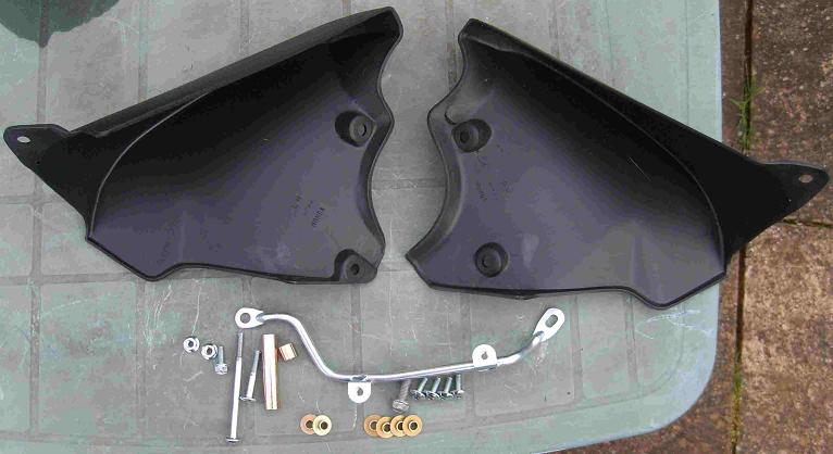
Here are all the
pieces. Left and right guards, 4 coach bolts, one long aluminium mounting
bracket, one long and one short spacing tube each with a bolt of corresponding
length, 4 shallow depth and two deeper shouldered washers , 2 x 10mm
nuts and two matching bolts.
The left and right
guards have L and R moulded into their inner faces so you can't get
them wrong.
|
|
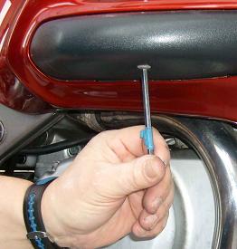
You
don't need to remove any part of the fairing but you do need to take off
the black plastic engine protector covers. Starting with the right hand
one, undo and remove the bolt on its underside.
|
|
|
|
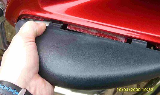
Now
squeeze the top and bottom faces of the cover very firmly to release the
tabs which clip it to the recess in the fairing. It's quite a hard squeeze
to pop the tabs free - there are upper and lower ones at the front and
the rear of the cover.
|
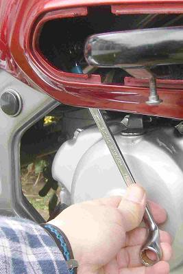
Use a 12mm ring
spanner to loosen the bolt which secures the rear of the right hand
engine protector bar to the chassis.
The bolt isn't very
obvious in this photo, but if you follow the line of the spanner, the
bolt is situated just above the blue tape at the spanner's throat. You
can see it quite clearly by eye once the crash bar cover is off.
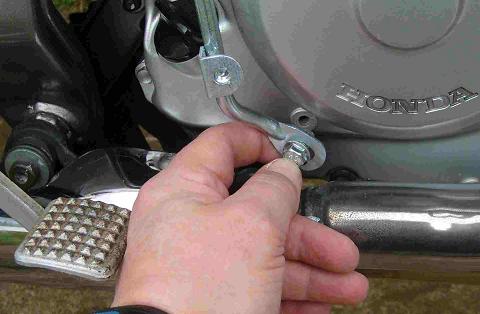
Once the bolt is
loose, reach in with your hand from underneath and unscrew the bolt
with your fingertips. This bolt you can now keep as a spare, as the
guard kit should come with a replacement bolt.
|
|
|
|
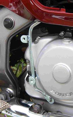
The long aluminium
strut fits on the right hand side of the bike. Its upper eye - this
is the one without the slot - goes at the top and is secured by the
replacement bolt which came with your kit. The bolt goes through the
strut's eye and back through the crash bar into the chassis. Drop some
ACF50 on the threads and replace the bolt, finger tight.
The bottom eye of
the strut has the slot. This is secured into the unused hole in the
crankcase, immediately above the exhaust heat shield. On my Deauville
this hole wasn't threaded but the bolt which came with the guard kit
cut its own thread as I tightened it.
Jukka Typpo
comments "I tried to drive the screw that came with the kit
to the crankcase hole without lubrication, hoping that it would just
cut the thread. It almost did, but when about 1 mm was left, the screw
got broken just under the head. The result is that I have 95% of the
thread length inside my crankcase, and the piece of the bolt that sticks
out is far too short to be taken out by regular hand tools. It is also
too short to do its job, it does not support the aluminium strut at
all. When mounting this screw, it probably is better to lubricate the
thread before driving the screw. Then turn 1/2 clockwise and 1/4 backwards
until the screw head makes the contact with the strut."
Mike
(Assybish) adds
: "Like you my Deau has no thread in the right side lower screw
hole so I used a 6mm tap VERY CAREFULLY as it is aluminium casting -
it worked beautifully and is very secure. Thought you might like to
suggest that on your page as I fear that self cutting using the screw
depends on the sharpness of the thread and it can vary and risks tearing
the whole out."
|
|
This
is how the right hand strut situates. Whan you are happy this is correct,
fully tighten the bolts.
|
|
|
|
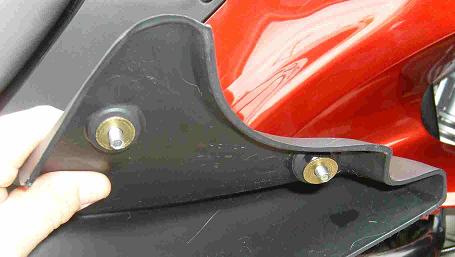
The
guard itself has brass collars which are inserted from the inside outwards
at the two rearmost holes. These collars stop the holding bolts from chewing
away the guard's plastic mouldings.
|
Offer the guard
up to the bracket and fasten into place with two of the coach bolts.
Don't do them up fully tight, but they should be firmly screwed in so
that the guard is held in its natural position.
Temporarily pop
the crash bar cover back into place but don't fix it with its underside
bolt.
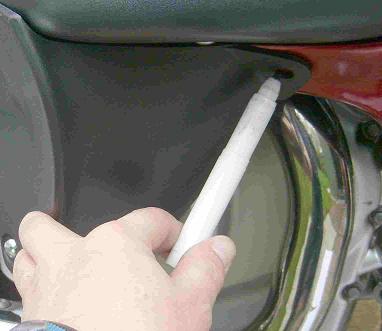
Holding the footguard
firmly against the crash bar cover so that there is minimal or no air
gap between them, use a felt pen or whiteboard pen to mark the position
of the third mounting hole which will be under the front edge of the
fairing.
|
|
|
|
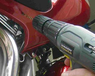
Remove the crash
bar cover and the footguard and drill a small pilot hole through the
centre of the marked place on the fairing.
Then use a 10mm
drill to make the mounting hole. This hole has to be large enough to
accommodate the inner bush of the brass collar.
|
|
Using
a sharp knife or blade, reach in and trim off any plastic which was turned
up by the action of drilling the mounting hole.
|
|
|
|
Again
using one of the brass collars to protect the body of the footguard, insert
a bolt from the underside and use one of the 10mm nuts to secure it. You
can reach into the space inside the fairing from the underside to get
the nut in the right place, but it's a little cramped.
Tighten
all of the mounting bolts, replace and re-bolt the crash bar black plastic
cover.
Here
is the right hand footguard completely mounted.
|
|
The
left guard is attached in a very different way. First remove the crash
bar cover as per its partner, but don't remove the rear crash bar mounting
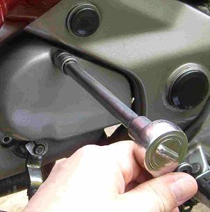
bolt. The left hand footguard is bolted to the upper and lower 8mm bolts
which secure the grey plastic engine cover which is directly next to the
gear lever.
|
|
|
|
Remove
the upper and lower 8mm bolts. Don't remove the grey plastic cover. Both
these 8mm bolts are now spares.
|
|
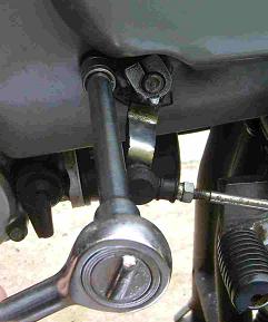
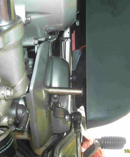
The
left hand footguard also uses two brass collars inserted from the inside
outwards at the rearmost two holes. The long hollow spacer bar and the
long matching bolt go on the inside face of the lower bolt, and the short
hollow spacer and bolt go on the upper hole. These replacement bolts will
screw into the places from where you just removed the two 8mm bolts.
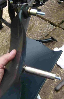
In
this picture the foot guard has its lower edge towards the camera.
|
|
|
|
Again
bolt up the two rear positions quite firmly and pop back the crashbar
cover. As you did with the other guard, hold it tight against the crashbar
cover and then mark the position of the third mounting hole.
Remove
the guard and crashbar cover and drill the pilot and then 10mm hole,
attach the guard and crash bar cover and tighten everything up just
as you did on the other side. Don't forget that the crash bar cover
has a securing bolt on its underside.
Here
is a photo from directly under the engine, pointing up and back so you
can see how the long extension spacer is situated.
|
|
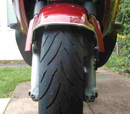
View
from the front, with both footguards fitted.
|
|
You are welcome
to comment on these
pages but you must manually remove the extra 'z' from the email address, and
put "Deauville" into the message header or body. If you don't do this,
I won't receive your message.
 the
Red Fox says : "After working with the supplied instructions
which came in the box with all the various pieces, I am of the opinion that
the handout was written by someone's Grandma after a bad night out. The diagrams
were poor and the text was minimal. What's confusing is that you'd kind of expect
that the left and right shields would be symmetrical in the way they attach
to the bike - but they are anything but symmetrical in this respect and the
various mountings are completely different between the left and right pieces.
I had to look very hard at everything before it was remotely clear how they
bolt on, and shortcomings in the text don't help. Grrrrr !! Anyway here is how
you do it."
the
Red Fox says : "After working with the supplied instructions
which came in the box with all the various pieces, I am of the opinion that
the handout was written by someone's Grandma after a bad night out. The diagrams
were poor and the text was minimal. What's confusing is that you'd kind of expect
that the left and right shields would be symmetrical in the way they attach
to the bike - but they are anything but symmetrical in this respect and the
various mountings are completely different between the left and right pieces.
I had to look very hard at everything before it was remotely clear how they
bolt on, and shortcomings in the text don't help. Grrrrr !! Anyway here is how
you do it."
